HUATUI
Integrity & Quality
NEWS
-
Welcome to our stand A110 CIAAF
-
Welcome to our stand W1.94 2025 CICEE
-
Welcome to our stand E1-A34 Yiwu Auto & Motorcycle Parts Expo 2025
-
Warmly celebrate the thoroughly successful ending of the 2025 China Hangzhou International Automobile and Motorcycle Parts Industry Expo
-
Welcome to our stand H7-R22 CAPAFAIR Hangzhou 2025
-
Welcome To Our Stand 9 E3617, BICES
-
Welcome to MIMS Automobility Moscow!
-
New Arrival ! Temperature Sensor For Caterpillar
-
New Arrival ! Fuel Water Level Sensor For Caterpillar
-
New Arrival ! Engine speed sensor For Caterpillar
-
New Arrival ! Crankshaft Postion Sensor For Detroit Diesel
-
New Arrival ! Solenoid Valve For Caterpillar
-
New Arrival ! Fuel Transfer Pump For Komatsu
-
New Arrival ! Solenoid Valve For Caterpillar
-
New Arrival ! Postion Sensor For Caterpillar
-
New Arrival ! Temperature Sensor For Caterpillar
-
New Arrival ! Solenoid Valve For Caterpillar--KEYOPO
-
New Arrival ! Speed Sensor For Caterpillar--KEYOPO
-
New Arrival ! Pressure Sensor For Caterpillar--KEYOPO
-
New Arrival ! Pressure Sensor For Caterpillar--KEYOPO
-
New Arrival ! Postion Sensor For Komatsu--KEYOPO
-
New Arrival ! Postion Sensor For Komatsu--KEYOPO
-
New Arrival ! Postion Sensor For Caterpillar--KEYOPO
-
Welcome to the Automechanika!
-
New Arrival ! Temperature Sensor For Caterpillar--KEYOPO
-
Welcome To Our Stand , Automechanika Shanghai
-
Happy New Year!
-
Do you want to know more about our product? Come and contact us!!
-
New Arrival ! Solenoid Valve For Caterpillar--KEYOPO
-
New Arrival ! Solenoid Valve For Caterpillar--KEYOPO
-
New Arrival ! Solenoid Valve For Komatsu--KEYOPO
-
New Arrival ! Solenoid Valve For BWM--KEYOPO
-
New Arrival ! Sensor For Komatsu--ROHOPE
-
Happy New Year!
-
New Arrival ! Solenoid Valve For Komatsu--KEYOPO
-
KEYOPO/RPHOPE Wish you a Merry Christmas!
-
Engine Starter Repair: How To Replace The Starter Solenoid
-
Common Bad Speed Sensor Symptoms
-
New Arrival ! Solenoid Valve For Caterpillar--KEYOPO
-
Advantages Of Solenoid Valves——KEYOPO
Sizing pipe and valves and calculating system pressure requirements(2)
来源:rember chen
|
作者:cynthia
|
发布时间 :2017-10-10
|
4591 次浏览:
|
Share:
Now
that we have sized these laterals, let’s have a look at the piping plan for
this entire sample system.

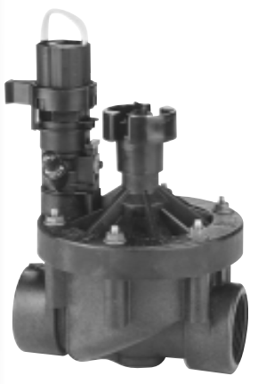
The main line has not yet been sized, nor has a component on the line just after the water meter — the backflow preventer. Backflow is the unwanted reverse flow of water in a piping system. A backflow preventer, of which there are several types, is a valve or valve assembly that physically blocks the potentially contaminated water in the irrigation system from flowing back into the domestic water supply.
This backflow prevention device, along with all the pipe and electric valves on the system, will need to be sized.
A few guidelines to assist you in sizing valves are listed below.

One caution about over-sizing automatic valves:
Occasionally, dealing with low pressures to begin with, will look for ways to reduce pressure loss. If the designer selects a large size valve because the flow loss is so low as to be unlisted on the performance chart, he or she may find the valve won't operate once the system is installed. There must be a minimum pressure loss through most types of automatic valves! The valves use this pressure differential to open and close. Lack of data in the manufacturer's performance chart is an indicator that the valve should not be used at the high or low flows in question.

The main line has not yet been sized, nor has a component on the line just after the water meter — the backflow preventer. Backflow is the unwanted reverse flow of water in a piping system. A backflow preventer, of which there are several types, is a valve or valve assembly that physically blocks the potentially contaminated water in the irrigation system from flowing back into the domestic water supply.
This backflow prevention device, along with all the pipe and electric valves on the system, will need to be sized.
A few guidelines to assist you in sizing valves are listed below.
•The
flow through the valve should not produce a loss greater than 10% of the static
pressure available in the main line.
•The
valve should either be the same size as the largest pipe in the lateral it
serves, or no more than one nominal size smaller than that pipe.
•The
valve should not be larger than the pipes in the lateral, unless a high flow
(equivalent to a larger size pipe) results from a split lateral.

One caution about over-sizing automatic valves:
Occasionally, dealing with low pressures to begin with, will look for ways to reduce pressure loss. If the designer selects a large size valve because the flow loss is so low as to be unlisted on the performance chart, he or she may find the valve won't operate once the system is installed. There must be a minimum pressure loss through most types of automatic valves! The valves use this pressure differential to open and close. Lack of data in the manufacturer's performance chart is an indicator that the valve should not be used at the high or low flows in question.

TEL:+86-577-88624645

FAX:+86-577-88623871

E-MAIL:info@huatui.com
FOLLOW US
Copy right © 2017 HUATUI GROUP
NAVIGATION BAR
FRIENDLY LINK


