HUATUI
-
Welcome to our stand A110 CIAAF
-
Welcome to our stand W1.94 2025 CICEE
-
Welcome to our stand E1-A34 Yiwu Auto & Motorcycle Parts Expo 2025
-
Warmly celebrate the thoroughly successful ending of the 2025 China Hangzhou International Automobile and Motorcycle Parts Industry Expo
-
Welcome to our stand H7-R22 CAPAFAIR Hangzhou 2025
-
Welcome To Our Stand 9 E3617, BICES
-
Welcome to MIMS Automobility Moscow!
-
New Arrival ! Temperature Sensor For Caterpillar
-
New Arrival ! Fuel Water Level Sensor For Caterpillar
-
New Arrival ! Engine speed sensor For Caterpillar
-
New Arrival ! Crankshaft Postion Sensor For Detroit Diesel
-
New Arrival ! Solenoid Valve For Caterpillar
-
New Arrival ! Fuel Transfer Pump For Komatsu
-
New Arrival ! Solenoid Valve For Caterpillar
-
New Arrival ! Postion Sensor For Caterpillar
-
New Arrival ! Temperature Sensor For Caterpillar
-
New Arrival ! Solenoid Valve For Caterpillar--KEYOPO
-
New Arrival ! Speed Sensor For Caterpillar--KEYOPO
-
New Arrival ! Pressure Sensor For Caterpillar--KEYOPO
-
New Arrival ! Pressure Sensor For Caterpillar--KEYOPO
-
New Arrival ! Postion Sensor For Komatsu--KEYOPO
-
New Arrival ! Postion Sensor For Komatsu--KEYOPO
-
New Arrival ! Postion Sensor For Caterpillar--KEYOPO
-
Welcome to the Automechanika!
-
New Arrival ! Temperature Sensor For Caterpillar--KEYOPO
-
Welcome To Our Stand , Automechanika Shanghai
-
Happy New Year!
-
Do you want to know more about our product? Come and contact us!!
-
New Arrival ! Solenoid Valve For Caterpillar--KEYOPO
-
New Arrival ! Solenoid Valve For Caterpillar--KEYOPO
-
New Arrival ! Solenoid Valve For Komatsu--KEYOPO
-
New Arrival ! Solenoid Valve For BWM--KEYOPO
-
New Arrival ! Sensor For Komatsu--ROHOPE
-
Happy New Year!
-
New Arrival ! Solenoid Valve For Komatsu--KEYOPO
-
KEYOPO/RPHOPE Wish you a Merry Christmas!
-
Engine Starter Repair: How To Replace The Starter Solenoid
-
Common Bad Speed Sensor Symptoms
-
New Arrival ! Solenoid Valve For Caterpillar--KEYOPO
-
Advantages Of Solenoid Valves——KEYOPO
Designer uses the principles of hydraulics to size all the components in the system and to ensure adequate flow and pressure to properly operate all the sprinklers on the project.
Each
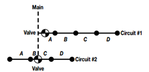
circuit has four, medium-sized rotor pop-up sprinklers that throw 47 ft (14,33 m) at 55 psi (3,8 bar), and each require 9.8 gpm (2,22 m3/h or 0,62 L/s). The designer has spaced them in an equilateral
triangular pattern at 50% spacing, but has chosen a different lateral pipe
configuration for each circuit. For reference, the various pipe sections of
each lateral have an identification letter.

The designer knows that the water supply must reach even the furthest sprinkler out on the line with a minimum of 55 psi (3,8 bar) to get the desired performance at the selected spacing.
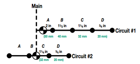
The route this sizing procedure follows along the various pipes in the circuit is called the critical circuit length. This route is defined as the longest path in the circuit that the water will have to travel. The critical length may also be described as the length between the valve and the most distal sprinkler.Looking at Circuit #1 in the example, it’s easy to see that the critical circuit length for this lateral includes all the pipe sections, section “A” through section “D.” The longest path from the valve to the most distal sprinkler is through all the lateral pipes.
In Circuit #2, the designer has split the lateral with the valve in the center of the circuit. The circuit is not split exactly in half. If it was, the designer could use either side of the circuit as the critical path. There is a slightly longer water path from the valve down through sections “C” and “D” to the furthest sprinkler. Sections “C” and “D,” therefore, make up the critical circuit length for example two. With the type of pipe selected and the critical lengths determined, the designer is ready to use the Class 200 PVC pipe chart and the 5 ft/s (1,5 m/s) method to size the lateral lines.

One of the advantages of splitting a sprinkler circuit is clearly evident in the above example. By splitting Circuit #2 and feeding it from a centrally located valve position, the designer has eliminated the need for the two larger pipe sizes. In addition to saving the cost of these bigger pipes, the cost of the larger fittings is gone and, if all the circuits of this size were similar, the contractor could standardize the materials inventory for the project. The circuit is also balanced with less pressure variation between sprinklers.


Copy right © 2017 HUATUI GROUP


